Mininet Hands-On: Emulation, SDN Controllers, and Custom Topologies
Mininet is network emulation software that lets you launch a virtual network — switches, hosts, and an SDN controller — all with a single command on one Linux machine. It is the fastest way to start learning about SDN and OpenFlow, test controller logic, and prototype topologies without owning a single piece of physical hardware.
This guide is structured as three progressive hands-on labs, each building on the previous one:
- Lab 1 — Launch the default topology, explore the CLI, and watch OpenFlow packets in Wireshark
- Lab 2 — Replace the default controller with Floodlight and POX, running both locally and on a separate VM
- Lab 3 — Build a custom full-mesh topology using a Python topology file and a standalone Python script
How Mininet Works
Before touching a command, it is worth understanding what Mininet actually creates when you run it.
Every host in Mininet is a Linux network namespace — an isolated network stack with its own interfaces, routing table, and ARP cache. Even though you are running on a single VM, each host is completely separated from the others at the network layer, just as real machines are.
Switches are real Open vSwitch (OVS) instances. They speak OpenFlow and connect to a controller over TCP.
Links between hosts and switches are virtual Ethernet (veth) pairs — pairs of virtual network interfaces connected back-to-back, like a patch cable in software. You can apply real traffic-shaping parameters (bandwidth, delay, packet loss) to these links using Linux’s tc (traffic control) subsystem.
The result is a network that behaves like real hardware. You can run actual applications — ping, iperf, curl, tcpdump — and get realistic results.
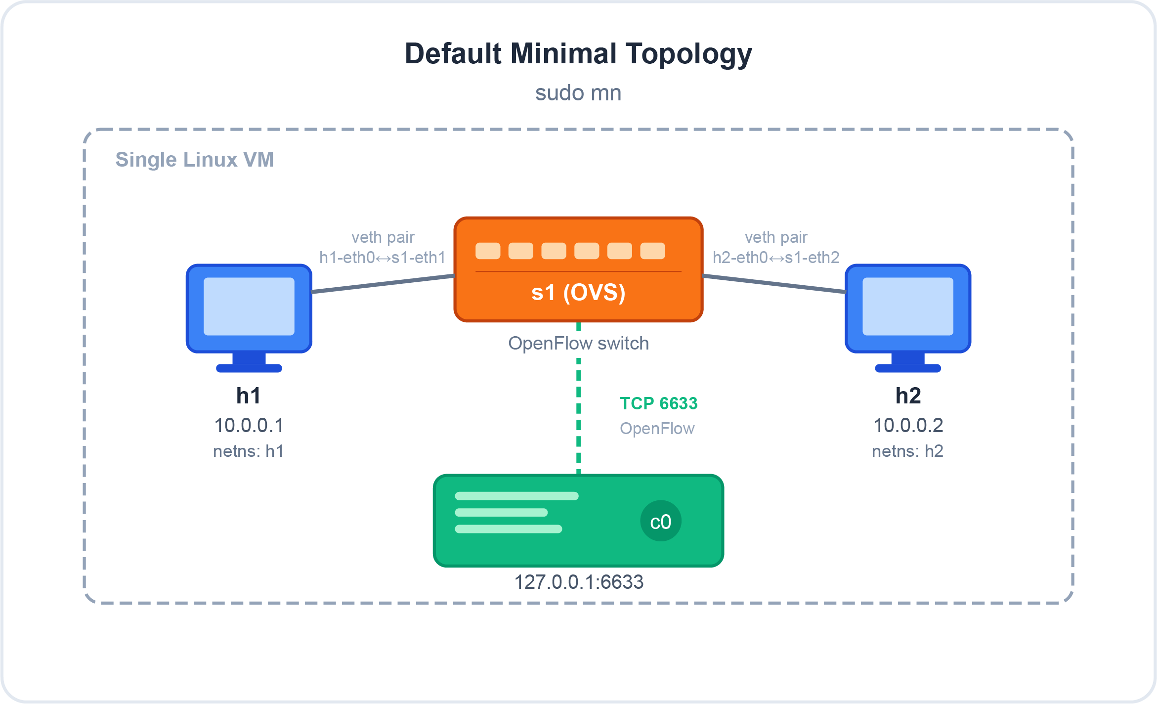 Default minimal topology created by
 sudo mn — two hosts in isolated network namespaces, one OVS switch, one OpenFlow controller
Lab 1: Your First Mininet Session
Setup
The easiest way to get started is the pre-built Mininet VM. Download it from mininet.org/download and import it into VirtualBox or VMware.
Default credentials: mininet / mininet
Once the VM is running, SSH into it with X11 forwarding enabled — you will need this for Wireshark and xterm windows later:
1

ssh -X mininet@<VM-IP-address>
To find the VM’s IP address, log into the VM console first and run:
1
2

ifconfig
# Look for eth0 inet addr — e.g. 10.0.0.11
Why
-X? The-Xflag enables X11 forwarding. Without it, commands likexterm h1andwiresharkwill fail because they need to render a graphical window on your local display.
Launch the Default Topology
1

sudo mn
That single command creates:
- 2 hosts (
h1,h2) in separate network namespaces - 1 OpenFlow kernel switch (
s1) - 1 OpenFlow reference controller (
c0) on127.0.0.1:6633
You are now at the Mininet prompt:
1

mininet>
Exploring the CLI
1
2
3
4
5
6
7
8
9
10
11
12
13
14
15
16
17
18

# Show all nodes in the network
mininet> nodes
available nodes are:
c0 h1 h2 s1

# Show detailed information about each node
mininet> dump
<Host h1: h1-eth0:10.0.0.1 pid=xxxx>
<Host h2: h2-eth0:10.0.0.2 pid=xxxx>
<OVSController c0: 127.0.0.1:6633 pid=xxxx>
<OVSSwitch s1: lo:127.0.0.1,s1-eth1:None,s1-eth2:None pid=xxxx>

# Show the network links (virtual ethernet pairs)
mininet> net
h1 h1-eth0:s1-eth1
h2 h2-eth0:s1-eth2
s1 lo:  s1-eth1:h1-eth0 s1-eth2:h2-eth0
c0
The net output is important: it confirms that h1-eth0 is connected to s1-eth1 and h2-eth0 is connected to s1-eth2. These are your veth pairs.
Running Commands on Hosts
You can run any Linux shell command on a host directly from the Mininet prompt by prefixing it with the host name:
1
2
3
4
5

mininet> h1 ifconfig
# Shows h1's network interfaces — you should see 10.0.0.1

mininet> h1 ping -c 3 h2
# Ping from h1 to h2
Observe something interesting: the first ping takes noticeably longer than the others.
1
2
3
4

PING 10.0.0.2 (10.0.0.2) 56(84) bytes of data.
64 bytes from 10.0.0.2: icmp_seq=1 ttl=64 time=23.4 ms   ← slow
64 bytes from 10.0.0.2: icmp_seq=2 ttl=64 time=0.412 ms  ← fast
64 bytes from 10.0.0.2: icmp_seq=3 ttl=64 time=0.389 ms  ← fast
This is OpenFlow in action. On the very first packet of any flow, the switch has no matching flow entry and must send a Packet-In message to the controller, then wait for a Flow-Mod reply telling it what to do. That round trip to the controller adds the extra latency you see on the first ping. After the flow is installed, subsequent packets match the cached entry and are forwarded at wire speed without involving the controller.
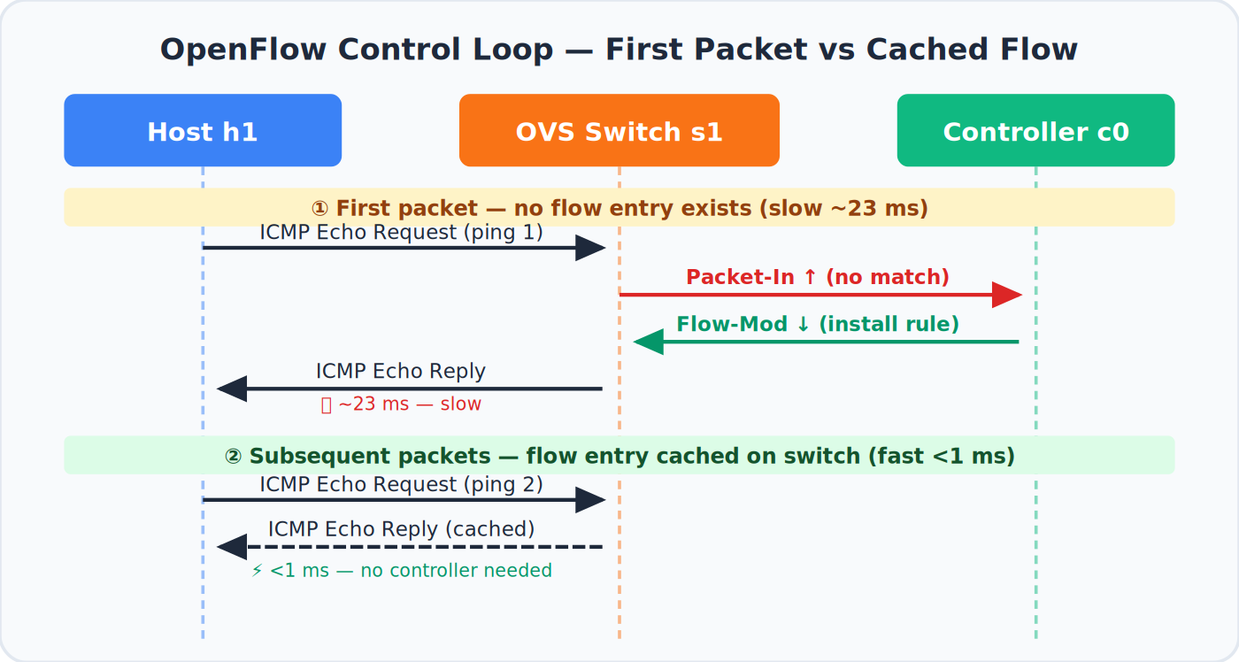 The OpenFlow control loop — the first packet triggers a Packet-In/Flow-Mod round trip; all subsequent packets match the cached flow entry
Opening an xterm Window
For more interactive work, you can open a terminal window for any host:
1

mininet> xterm h1
A new terminal window opens, logged in as h1. From there you can run any command as if you were physically at that machine:
1
2
3
4

# Inside the h1 xterm:
ping -c 3 10.0.0.2    # Ping h2 by IP (hostname resolution not available here)
ifconfig               # Confirm IP is 10.0.0.1
tcpdump -n            # Capture packets on h1's interface
Open a second terminal in Mininet and generate traffic to observe it in tcpdump:
1
2

# In the Mininet CLI:
mininet> h1 ping h2
Connectivity and Bandwidth Tests
1
2
3
4
5
6
7
8
9
10
11
12
13
14

# Ping between all host pairs
mininet> pingall
*** Ping: testing ping reachability
h1 -> h2
h2 -> h1
*** Results: 0% dropped (2/2 received)

# TCP bandwidth test between h1 and h2
mininet> iperf
*** Iperf: testing TCP bandwidth between h1 and h2
*** Results: ['214 Mbits/sec', '215 Mbits/sec']

# UDP bandwidth test
mininet> iperfudp
Simulating WAN Links with Delay and Bandwidth Limits
Exit the current session and restart with link parameters:
1
2

mininet> exit
sudo mn -c   # Always clean up before starting a new session
Now launch with a 10 Mbps bandwidth limit and 10 ms delay per link:
1

sudo mn --link tc,bw=10,delay=10ms
Run iperf again — instead of ~214 Mbps, you will see approximately 9.5 Mbps because the link is capped at 10 Mbps. The 10 ms delay each way (20 ms RTT) also noticeably affects TCP throughput due to increased window fill time.
1
2

mininet> iperf
*** Results: ['9.54 Mbits/sec', '9.61 Mbits/sec']
This is genuinely useful for testing how your application behaves over a constrained WAN connection — all on a single laptop.
Built-in Topology Reference
Mininet ships with four ready-made topologies selectable from the command line:
| Topology | Command | Switches | Hosts |
|---|---|---|---|
| minimal | sudo mn |
1 | 2 |
| single | sudo mn --topo single,4 |
1 | 4 |
| linear | sudo mn --topo linear,4 |
4 (chained) | 4 (one each) |
| tree | sudo mn --topo tree,depth=2,fanout=2 |
3 (root + 2 children) | 4 |
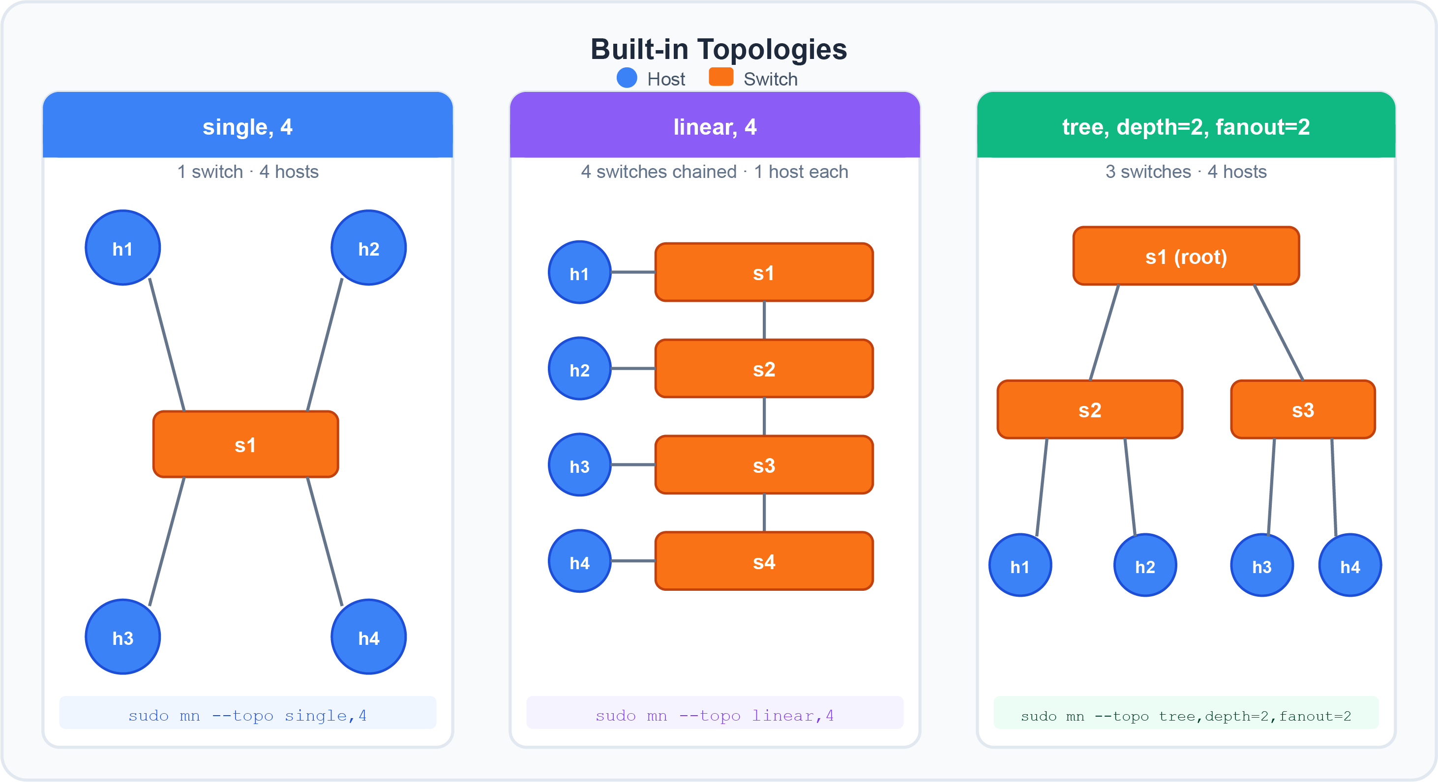 The three most common non-default topologies: single switch with multiple hosts, linear switch chain, and two-level tree
Watching OpenFlow with Wireshark
Open a second SSH session to the Mininet VM (with -X again) and launch Wireshark:
1
2
3

# Second terminal:
ssh -X mininet@<VM-IP>
sudo wireshark &
In Wireshark:
- Start a capture on interface
lo(loopback) - Apply the display filter:
openflow_v1
The controller and switch communicate over the loopback interface because they are both local to the same VM.
Back in the Mininet CLI:
1

mininet> pingall
Stop the Wireshark capture and inspect the packets. You will see:
- Packet-In messages: the switch forwarding unknown packets up to the controller for a forwarding decision
- Flow-Mod messages: the controller installing flow entries back onto the switch
This is the core OpenFlow control loop — and you just captured it live.
Lab 2: Remote SDN Controllers
The default Mininet controller is useful for learning but limited in capability. In real SDN deployments you replace it with a full-featured controller like Floodlight (Java-based) or POX (Python-based).
Understanding “Remote” Controllers
When Mininet is told to use a remote controller, it means the controller process runs outside of Mininet itself — either on the same VM or a completely separate machine. The switch connects to it over TCP (default port 6633 or 6653).
1
2

sudo mn --controller remote              # Look for controller at 127.0.0.1:6633
sudo mn --controller remote,ip=10.0.0.12,port=6633  # Explicit IP and port
Scenario A: Floodlight Running Locally
Both Floodlight and Mininet run on the same VM. The switch connects to Floodlight over the loopback interface (127.0.0.1:6633).
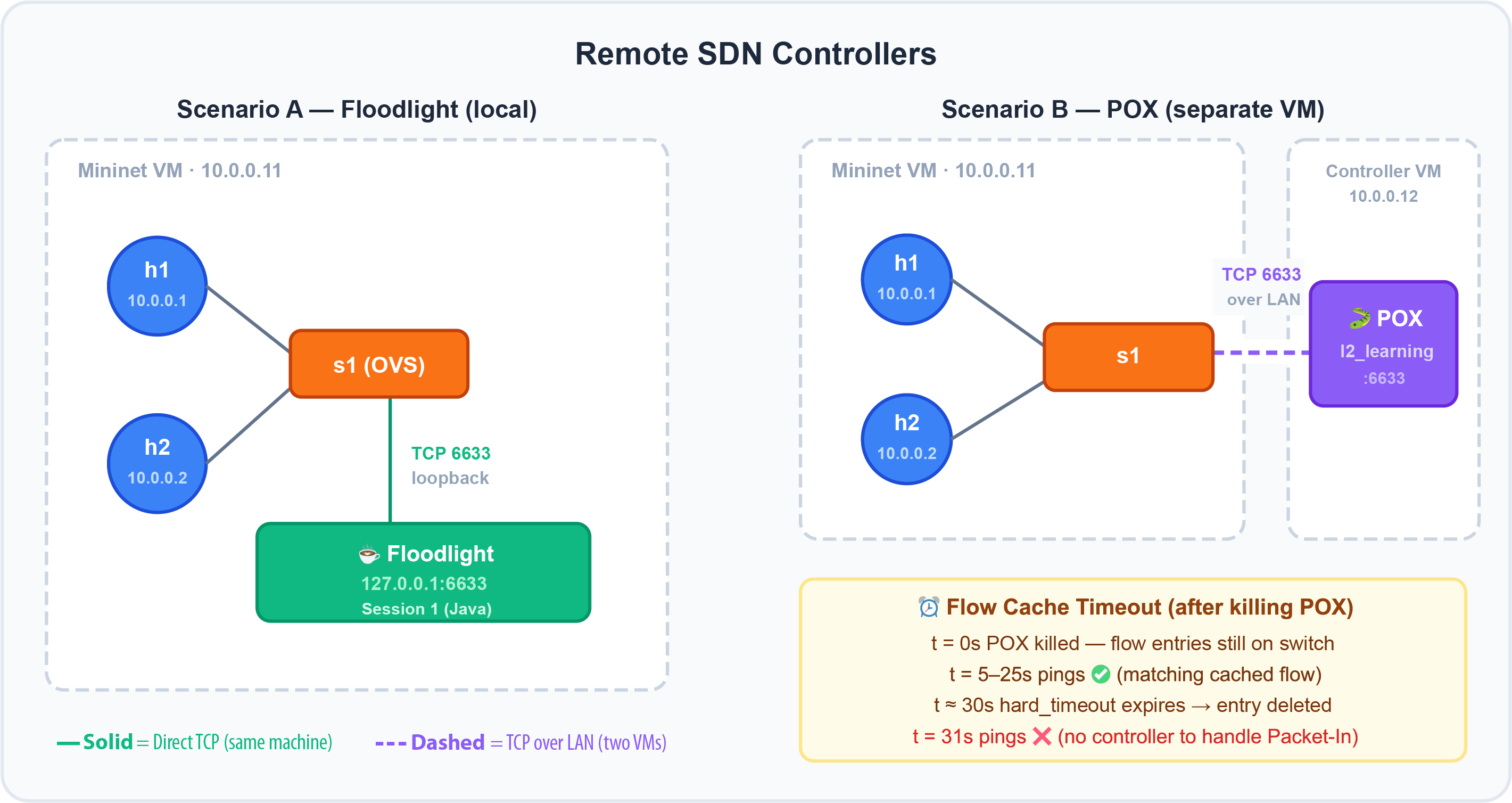 Left: Floodlight running locally (both sessions on the same VM). Right: POX on a separate VM connected over the LAN. The timeout table shows what happens when the controller is killed.
Step 2 — In the first session, start Floodlight:
1
2
3
4

# Session 1 — Floodlight
cd ~/floodlight
java -jar target/floodlight.jar
# Watch for: "Listening for switch connection on port 6633"
Step 3 — In the second session, start Mininet pointing at Floodlight:
1
2
3

# Session 2 — Mininet
sudo mn --controller remote
# Default connects to 127.0.0.1:6633 — where Floodlight is listening
Step 4 — Check the Floodlight console. You should see a message showing the switch’s DPID (Datapath ID) has connected. The DPID is a 64-bit identifier unique to each OVS switch.
Step 5 — Verify connectivity:
1
2

mininet> pingall
# Both hosts should reach each other — Floodlight's forwarding module is working
Step 6 — Kill Floodlight with Ctrl+C in session 1, then run pingall again:
1
2

mininet> pingall
# Now you get timeouts — no controller, no forwarding decisions for new flows
This demonstrates a fundamental SDN concept: the control plane (controller) and data plane (switch) are separated. Remove the controller and the switch cannot handle new traffic.
Cleanup: Always run
sudo mn -cafter finishing a session. This removes zombie processes, OVS bridge configurations, and virtual interfaces that would prevent the next session from starting cleanly.
Scenario B: POX Running on a Separate VM
This scenario is more realistic: Mininet runs on one machine, the controller runs on another, connected over a real (or virtual) network. The diagram above (right side) shows this layout — s1 connects to POX at 10.0.0.12:6633 over the LAN.
On the controller VM (e.g. at 10.0.0.12):
1
2
3

cd ~/pox
python pox.py forwarding.l2_learning
# POX starts its L2 learning switch and listens on port 6633
On the Mininet VM:
1

sudo mn --controller remote,ip=10.0.0.12,port=6633
Mininet starts and the switch immediately tries to connect to POX at 10.0.0.12:6633. Watch the POX console — you will see the switch DPID appear as soon as the connection is established.
1
2

mininet> h1 ping h2
# Working — POX's l2_learning is forwarding traffic
Now kill POX on the controller VM:
1

# Controller VM: Ctrl+C
Observe what happens in Mininet. The pings continue working for a while, then eventually time out. This is because:
- POX had already installed flow entries on the switch via Flow-Mod messages
- Those entries are cached on the switch until their timeout expires
- While the cache is valid, the switch forwards without consulting the controller
- Once the hard timeout expires, new Packet-In messages have no controller to answer them — traffic stops
The flow cache timeout behaviour is illustrated in the bottom-right panel of the diagram above.
This is a critical design consideration for production SDN: what happens when the controller goes away? The fail-mode setting on OVS (standalone vs. secure) determines whether the switch falls back to normal learning-switch behaviour or drops all traffic.
Lab 3: Custom Topologies
The built-in topologies (minimal, single, linear, tree) cover many cases, but real networks are rarely that regular. Mininet gives you two ways to define custom topologies.
The Target Topology
For both methods below, we will build the same topology: four switches in a full mesh (every switch connected to every other switch) with two hosts attached:
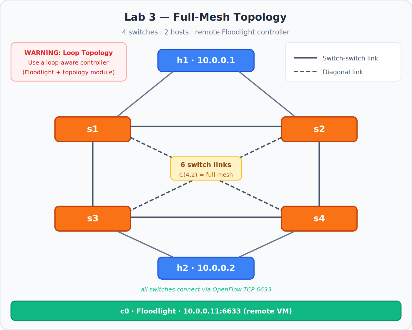 Full-mesh topology with 6 inter-switch links (C(4,2) = 6). Hosts h1 and h2 attach to opposite corners. All switches connect to Floodlight via OpenFlow.
Important: A full-mesh switch topology creates loops. Always use a topology-aware SDN controller (like Floodlight with its topology and forwarding modules, or POX with spanning tree) for loop topologies. A simple learning-switch controller without loop detection will cause a broadcast storm that can crash the emulation — or your real laptop. Floodlight’s topology module detects and prevents packets from looping by only activating non-looping paths.
Method 1: Custom Topology File with the mn Command
Mininet supports loading a topology from a Python file and passing it to the mn command. You do not need to know Python deeply — the file follows a simple template.
Navigate to the custom topology directory:
1
2
3

cd ~/mininet/mininet/custom
cat README
# Shows: sudo mn --custom custom_example.py --topo mytopo
Look at the example file topo-2sw-2host.py to understand the structure:
1
2
3
4
5
6
7
8
9
10
11
12
13
14
15
16
17
18
19
20
21
22

"""
Example: host — switch — switch — host
"""
from mininet.topo import Topo

class MyTopo(Topo):

    def build(self):
        # Add hosts
        leftHost  = self.addHost('h1')
        rightHost = self.addHost('h2')

        # Add switches
        leftSwitch  = self.addSwitch('s1')
        rightSwitch = self.addSwitch('s2')

        # Add links
        self.addLink(leftHost,   leftSwitch)
        self.addLink(leftSwitch, rightSwitch)
        self.addLink(rightSwitch, rightHost)

topos = {'mytopo': (lambda: MyTopo())}
Naming rules: host names must follow the pattern h + unique integer (e.g. h1, h2). Switch names must follow s + unique integer (e.g. s1, s2). Do not use arbitrary names or Mininet may behave unpredictably.
The example creates a simple inline chain: h1 — s1 — s2 — h2, with all traffic flowing through both switches.
1
2
3
4
5
6
7
8
9
10
11
12
13
14
15
16
17
18
19
20
21
22
23
24
25
26
27
28
29
30
31
32
33
34

"""
Full-mesh topology: 4 switches, 2 hosts.
All 4 switches are connected to each other (6 links between switches).
h1 attaches to s1, h2 attaches to s4.

WARNING: Use a loop-aware SDN controller (e.g. Floodlight with topology
module) or this topology will cause a broadcast storm.
"""
from mininet.topo import Topo

class MyTopo(Topo):

    def build(self):
        # Add hosts
        h1 = self.addHost('h1')
        h2 = self.addHost('h2')

        # Add four switches
        s1 = self.addSwitch('s1')
        s2 = self.addSwitch('s2')
        s3 = self.addSwitch('s3')
        s4 = self.addSwitch('s4')

        # Attach hosts
        self.addLink(h1, s1)
        self.addLink(h2, s4)

        # Full mesh between switches using a nested loop
        switches = [s1, s2, s3, s4]
        for i, sw_a in enumerate(switches):
            for sw_b in switches[i+1:]:
                self.addLink(sw_a, sw_b)

topos = {'mytopo': (lambda: MyTopo())}
Run it with Floodlight on a remote VM:
1
2
3
4

sudo mn \
    --custom mesh.py \
    --topo mytopo \
    --controller remote,ip=10.0.0.11
Verify:
1
2
3

mininet> dump     # 2 hosts, 4 OVS switches, 1 remote controller
mininet> net      # Confirm full-mesh links between all 4 switches
mininet> pingall  # Should show 0% packet loss
Method 2: Standalone Python Script
The second approach gives you more control. Instead of a topology-only file used with mn, you write a complete Python script that creates the network, starts it, opens the CLI, and cleans up.
This is the pattern used in Mininet’s own examples/ directory. Start by studying emptynet.py in ~/mininet/mininet/examples/ to understand the boilerplate.
Here is the equivalent full-mesh topology as a standalone script:
1
2
3
4
5
6
7
8
9
10
11
12
13
14
15
16
17
18
19
20
21
22
23
24
25
26
27
28
29
30
31
32
33
34
35
36
37
38
39
40
41
42
43
44
45
46
47
48
49
50
51
52
53
54
55
56
57
58
59
60
61
62
63
64
65
66
67
68
69
70
71
72
73
74
75
76
77

#!/usr/bin/env python3
"""
mesh.py — Full-mesh Mininet topology (standalone script).

Four switches fully meshed, two hosts, remote Floodlight controller.

Usage:
    sudo python3 mesh.py

WARNING: Use a loop-aware controller. See topology warning above.
"""

from mininet.net import Mininet
from mininet.node import RemoteController, OVSKernelSwitch
from mininet.link import TCLink
from mininet.log import setLogLevel
from mininet.cli import CLI

def build_mesh():
    """Build and run a full-mesh 4-switch, 2-host topology."""

    # Point to Floodlight running on a separate VM
    controller_ip   = '10.0.0.11'
    controller_port = 6633

    net = Mininet(
        switch=OVSKernelSwitch,
        link=TCLink,
        controller=None    # We add the controller manually below
    )

    # Add the remote controller
    c0 = net.addController(
        'c0',
        controller=RemoteController,
        ip=controller_ip,
        port=controller_port
    )

    # Add hosts (defaults to 10.0.0.1 and 10.0.0.2)
    h1 = net.addHost('h1')
    h2 = net.addHost('h2')

    # Add four switches
    s1 = net.addSwitch('s1')
    s2 = net.addSwitch('s2')
    s3 = net.addSwitch('s3')
    s4 = net.addSwitch('s4')

    # Attach hosts to switches
    net.addLink(h1, s1)
    net.addLink(h2, s4)

    # Full mesh between all four switches
    switches = [s1, s2, s3, s4]
    for i, sw_a in enumerate(switches):
        for sw_b in switches[i+1:]:
            net.addLink(sw_a, sw_b)

    # Start the network
    net.start()

    print('\n=== Network started ===')
    print(f'Controller: {controller_ip}:{controller_port}')
    print(f'Hosts:      {[h.name for h in net.hosts]}')
    print(f'Switches:   {[s.name for s in net.switches]}')
    print()

    # Drop into the interactive Mininet CLI
    CLI(net)

    # Clean up when the user exits the CLI
    net.stop()

if __name__ == '__main__':
    setLogLevel('info')
    build_mesh()
Run it directly — no mn command needed:
1

sudo python3 mesh.py
The output and behaviour are identical to Method 1. Inside the CLI:
1
2
3

mininet> dump    # Same nodes as before
mininet> net     # Same full-mesh links
mininet> pingall # 0% packet loss
The difference is that Method 2 gives you full programmatic control. You can add automated tests, modify the topology at runtime, collect statistics, and integrate with CI/CD pipelines — all within the same script.
Comparison: Two Methods for Custom Topologies
| Aspect | Method 1 — Topology File | Method 2 — Python Script |
|---|---|---|
| Entry point | sudo mn --custom file.py --topo name |
sudo python3 script.py |
| Complexity | Low — topology class only | Medium — full Mininet API |
| Controller | Specified on mn command line |
Configured in the script |
| Automation | Limited | Full — tests, logging, results |
| Flexibility | Topology structure only | Everything: nodes, links, IPs, tests |
| Best for | Quick topology experiments | Production scripts, CI, research |
Lab Summary: What You Observed
Working through these three labs, you have seen the following SDN and Mininet concepts in action:
The first-packet latency effect — OpenFlow requires the first unknown packet to be sent to the controller before it can be forwarded. This is why the first ping is always slower. Once the flow entry is installed, subsequent packets match it and are forwarded at line rate without controller involvement.
Flow entry caching and timeouts — when you killed the POX controller, pings kept working until the flow entries on the switch expired. This is the hard timeout in action. After expiry, with no controller to handle Packet-In messages, traffic stopped.
The broadcast storm danger — a full-mesh (looped) topology is only safe with a controller that implements loop detection. Floodlight’s topology module handles this; a simple learning switch controller does not. Always match your topology to your controller’s capabilities.
Two ways to build topologies — the topology file is quick for experiments. The Python script is more powerful for anything involving automation, custom IPs, per-link parameters, or programmatic testing.
Quick Reference
1
2
3
4
5
6
7
8
9
10
11
12
13
14
15
16
17
18
19
20
21
22
23
24
25
26
27
28

# Start / stop / clean up
sudo mn                                         # Default: 2 hosts, 1 switch, default controller
sudo mn --topo single,4                         # 1 switch, 4 hosts
sudo mn --topo linear,4                         # 4 switches in a chain, 1 host each
sudo mn --topo tree,depth=2,fanout=2            # 2-level tree, fan-out 2
sudo mn --link tc,bw=10,delay=10ms              # 10 Mbps links with 10ms delay
sudo mn --controller remote,ip=10.0.0.12,port=6633  # Remote controller
sudo mn --custom mesh.py --topo mytopo         # Custom topology file
sudo mn -c                                      # Clean up after crash

# CLI essentials
nodes                            # List all nodes
dump                             # Detailed node info
net                              # Show links
h1 ifconfig                      # Run command on a host
h1 ping -c 3 h2                  # Ping between hosts
pingall                          # Ping all pairs
iperf                            # TCP bandwidth h1→h2
xterm h1                         # Open terminal for h1
sh ovs-ofctl dump-flows s1       # Show OpenFlow flows on s1
exit                             # Exit Mininet

# POX (from ~/pox directory)
python pox.py forwarding.l2_learning            # L2 learning switch
python pox.py openflow.spanning_tree forwarding.l2_pairs  # Loop-safe

# Standalone script
sudo python3 mesh.py             # Run custom topology script
Conclusion
Mininet removes all barriers to learning SDN. There is no hardware to buy, no rack to cable, no firmware to update. A topology that would take a team days to assemble in a lab takes seconds on a laptop. The OpenFlow packets you captured in Wireshark, the controller disconnect behaviour you observed with POX, and the broadcast-storm warning around loop topologies — these are all real networking concepts, observed in a real (if emulated) environment.
The natural next steps are: exploring more of Mininet’s examples/ directory (it contains scripts for multipath routing, QoS, bandwidth testing, and more), writing your own OpenFlow controller application in Ryu or POX, and eventually testing your controller logic in a CI pipeline where Mininet runs as part of an automated test suite.
Additional Resources
- Mininet Official Website
- Mininet Walkthrough — the definitive getting-started guide
- Mininet Python API Reference
- Floodlight SDN Controller
- POX Controller Wiki
- Ryu SDN Framework — modern Python controller
- OpenFlow Specification